Gena: the battery
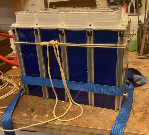
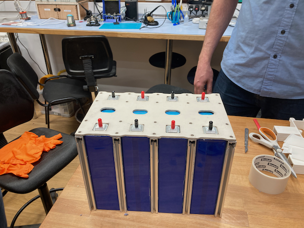
Lithium Iron Phosphate batteries expand and contract as they charge and discharge. For this reason, they should be compressed gently. If this is not done, their life is shortened. When charging and discharging at high current, they can also get warm. For this reason, Gena is constructed in alternating layers of aluminium extrusion and prismatic cell (230AH). The aluminium extrusion has the additional benefit of providing plenty of flexibility for secure installation since it can accept T-nuts in its channels.
To keep compression, straps or rope can be used, the picture below shows two options: a simple strap that is difficult to adequately tension, and a rope tied in a trucker's hitch which is much easier. The rope is tied to shoulder bolts with wide heads as used with motorcycles fixed into the channel in the aluminium extrusion using T-nuts. The final version will use aramid fibre rope of 5mm because it is strong, abrasion resistant and slightly elastic.
Gena is designed to be installed in a boat so is at the very least water resistant. This is accomplished with a rubber mat that acts as a gasket and a 3D printed cofferdam assembly that is screwed into rivet nuts installed into the top of the aluminium extrusions. On top of that is a gasket and a transparent lid that facilitates easy inspection.
Since the purpose is to power an electric engine, 48V is required. Rather than build one large battery, it is better to build four smaller ones arranged in series. This way transportation and installation is easier, and, if for some reason the battery pack must be broken up because a standard 12V battery is needed elsewhere, it is straightforward to do so. We still use a 48V BMS designed for 16 cells, however, and the balancing leads are exposed in a 7 pin waterproof connector -- 5 pins are used for balancing and the remaining 2 for a thermistor to sense temperature.
Cell sandwich assembly
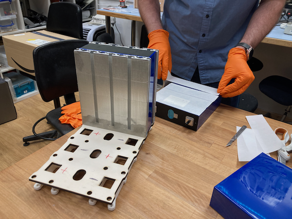
Cells are assembled with the help of a jig, sandwiched between the aluminium extrusions used for air flow. After being carefully cleaned with isopropanol (rubbing alcohol) they are stuck together with very sticky double sided tape.
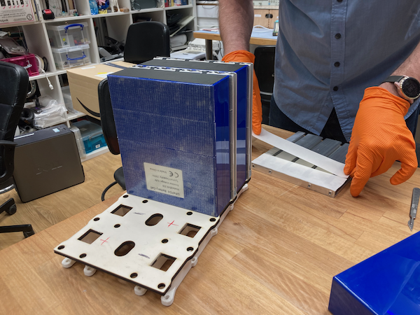
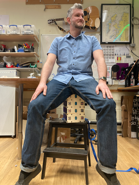
To help ensure the surfaces are well adhered, the entire battery is held under compression for several minutes.
The completed cell sandwich then gets a rubber mat. Rubber can be cut on the laser cutter but it makes a terrible smell.

Cofferdam
The goal of the cofferdam assembly is to segregate the battery connections from each other, and from the outside world as well as to provide channels for the cabling. We do this with a cofferdam assembly, 3D printed, though for production it could easily be injection moulded. The bottom has a bead to bite into the rubber mat on top of the battery. The channels for the power cables are meant to be filled with butyl tape or similar sealant. On top goes a gasket and a transparent perspex lid. The STL file is available but needs to be redone in a parametric way to suit different cell geometries.

Bus bars
Some careful choice of bus bar is required. Since the battery can be expected to expand and contract, rigid bus bars are not appropriate. After several experiments with copper braid, these commercially available bus bars made of many layers of copper sheet with ends that have been pressed do the trick.

BMS Connection

We use waterproof SP21 7 pin connectors to connect the BMS to each battery. The balancing current is specified as 5A implying 1.5mm^2 cabling. The connectors are keyed, with three keyways. On the side of the connector with two keyways closest together, there is also a white marking. The white marking is between pins 1 and 2.
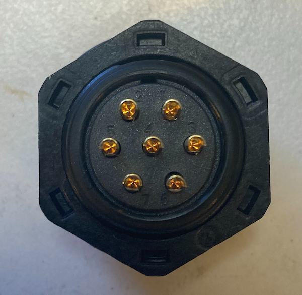
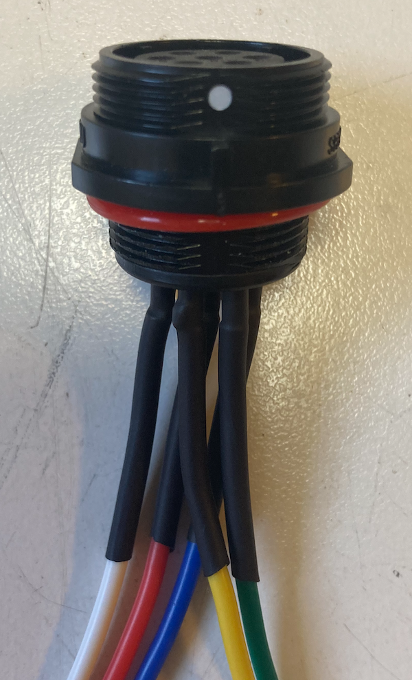
The pin allocation and wiring colours are as follows,
| Pin | Colour | Function |
|---|---|---|
| 1 | Green | +0V |
| 2 | Yellow | +3V |
| 3 | Blue (or Brown) | +6V |
| 4 | Red | +9V |
| 5 | White | +12V |
| 6 | Future | |
| 7 | Future |